Pico/mPython - smart car DIY
Time for a new robot approach: building a 'smart car' platform. Having some Arduino Uno experiences some years back, it's time to learn something new:
- Want to use Pico-W board
- Learn microPython
- Using new software IDE: Visual Studio Code
- Want learn & experience with some robot control, dead reckoning & odometry. Basically driving a robot to a wanted position..
That would make the robot a bit smarter, doesn't it?
After reading this inspiring medium article: "Pico Bot" by Doug Blanding, there is no reason to wait any longer.
This post is about:
- Starting building & learning on the way.
Major software upgrade:
- Jump directly to the: Mobile Robot Platform.
The Build
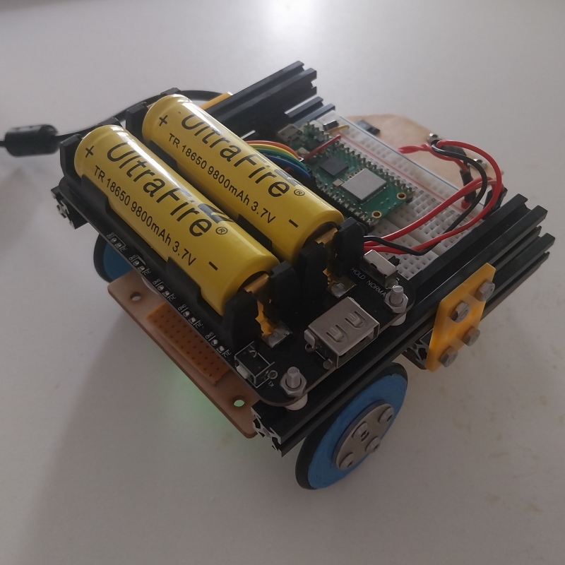
It's the updated version, with batteries mounted on top of the wheels. (Less slip, better results. Thanks Joep.)
Bits & pieces
There are a lot of robot parts laying around, so let's use them:
- 2x N20 "500rpm" cheap motor with encoder
- 1x Caster wheel
- 1x RPi Pico-W
- 1x DRV8835 Dual Motor Driver Carrier
- 1x 18650 Lithium Battery Shield V8 (2 batteries)
- 1x breadboard + jumper wires, on/off switch, piece of prototyping PCB board and some PCB connectors (both male & female)
- 1x laser-cutted piece of plywood
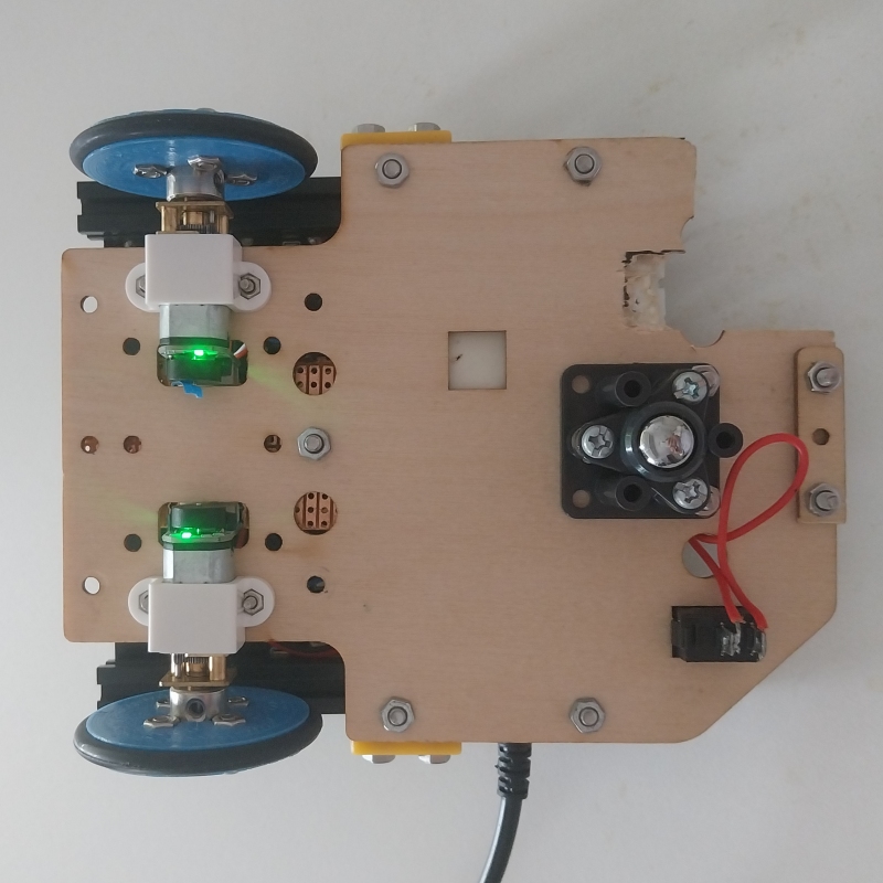
Bottom side
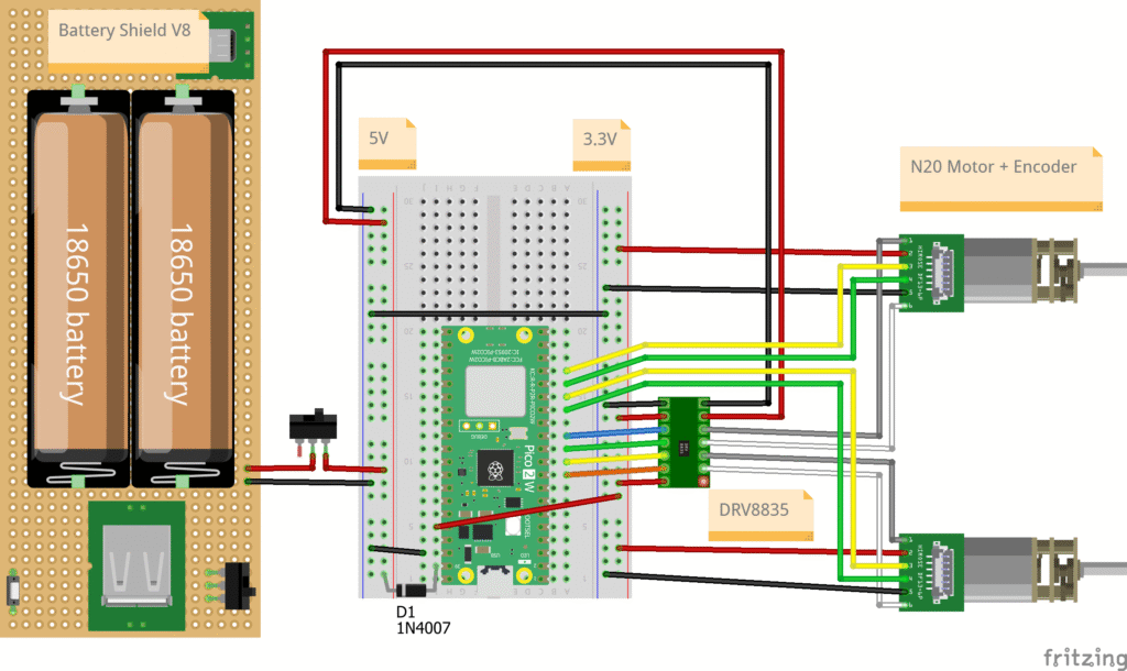
Electronics
Connection diagram used:
Battery Shield V8 & powering the Pico
The battery shield has an "activation button" and with the "mode switch" on "hold" position, the activation button could be used to turn the shield on (1 click) or off (2 clicks).
An additional on/off button, controlling the shield output power.
For powering the RPi Pico: watch this excelent video:
Power for the Raspberry Pi Pico.
So, being able to connect both your battery and upload code via USB, you need some kind of protection. According official Raspberry Pi documentation, it's best using a P-channel mosfet. A schottky diode (1n5817) is a good alternative, but I don't have that either:

So I'm using a 1N4007 instead, which seems to work up till now. (This diode has a voltage drop of 0.7V, which is basically burning energy from the battery supply..) ToDo: Order some mosfets...
DRV8835 modes
This DRV8835 motor controller has 2 modes:
- MODE pin connected to 5V: Enable/Phase mode.
- MODE pin not connected: In/In mode.
(The pin has an internal pulldown resistor.)
I'm using the enable/phase mode. This requires only 1x PWM signal and 1x direction pin per motor. Having the ability to: Brake, Reverse & Forwards.
So I'm not able to use the 'coasting' function. The drive has another optional feature: 'sleep' mode, by making VCC=0 Volt.

Pins used on Pico-W
Connection diagram:

Software preperation
Firmware update: Pico-W
Download the latest Pico-W firmware from microptyhon.org and follow procedure with boot-select etc.
Currently using:
- "
RPI_PICO_W-20240602-v1.23.0.uf2" - "RPI_PICO_W-20250911-v1.26.1.uf2"
Install Visual Studio Code
Download and install Visual Studio code.
Watch YouTube: How to Use VSCode with Raspberry Pi Pico W and MicroPython.
Compared to the YouTube, the VSCode extensions seems to be upgraded and renamed: "MicroPico" extension. (Thanks Paul Ober, for making this nice extension available to all of us.)

(The extension also requires some other packages, which is nicely documented. MicroPython is updated to version: 4.3.0.)
Blinky
Now the RPi Pico is powered by the USB only, the LED on the Pico could already be tested, see above youtube movie.
Learning to work with VSC & RPi Pico...
I'm just starting and learning on the way. Some learnings sofar:
- Starting a new project: "import machine" is not reconized:
For every new VSC/RPi-Pico project, you have to:
- First of all open a new folder and
- run > MicroPico > Configure Project command, via Ctrl+Shift+P.
This will install all necessary microPython links to your project.
- Error: "Module not found":
Maybe it's just me, but uploading blinky code to the Pico was quite simple, by selecting the 'Run current file' button. But now I like to include a 2nd module, from a seperate file (encoder_portable.py). The VSCode screen does not report an error, but pressing the 'Run current file' button, did not upload this additional 'module' on the Pico! So when using additonal microPtyhon files/modules, all project files need to be uploaded... (Tnxs Iwan!)

(ToDo: Understand difference between: 'running current file' and uploading files to the Pico..)
- How to run script remote after booting Pico, w/o USB connected:
When the Pico is connected to VSCode, it's not running automatically the 'main.py' file. But if the USB cable is disconnected and the Pico is re-powered by the batteries, it first tries to run 'boot.py' (for setting up internal devices etc) and then continous to execute 'main.py' if available.
Example of working 'main.py', needs only 2 code lines, for running a different 'module.py':
main.py
-------------
import motors
motors.run()- Running specific script/function from a module (name == "main"):
While the 'main.py' and other code is still copied on the Pico, it's still possible to run test code inside your module. Say the motor module needs to be tested, but this test code should not automatically start, while running the main module.
With the USB & VSCode connected, the 'motors.py' could be activated by 'Run current file'. Now code following 'if __name__ == "__main__":' will be exectued.
Optional, the test code could be defined as a function inside the motors.py module:
motors.py
---------

def run_test2()
	print('test case')

#-----------------------------------------------------------------------
if __name__ == "__main__":
run_test2()- Blocked RPi Pico:
After some (other) faulty code, while playing with USB communication, the Pico was completely bricked. 🙁 VSCode was not able to connect to the Pico at all. For unblocking your RPi Pico, upload during bootsel the 'flash-nuke.uf2' file, see also: How To Un-Brick Your Stuck Raspberry Pi Pico.
- ToDo: Coding remotely on the Pico:
Wouldn't it be fantastic programming the Pico robot remotely?
(Getting Started with REPL on the Raspberry Pi Pico using Rshell)
No USB cable needed, unless the Pico is bricked.
This also enables a standard USB connection with PC or Paspberry Pi 4, which might control the Pico someday...
Driving motors & measure power consumption
Now hardware, firmware & software seems to run, it's time for spinning motors. The duty cycle signals from the Pico will define the speed of the motors in a range of [0..65536] → 0-5 [Volt] on the pico pin.
The PWM frequency could be set between 0 and 250 kHz, according the DRV8835 datasheet. Re-using the 1000Hz setting from Doug seems to work for this driver too. This frequency setting may influence driver performance.
(ToDo: Some PWM-frequency testing..)
Basic code:
# imports:
from machine import Pin, PWM

# setup motor pin:
pinMtrDir_L = Pin(6, Pin.OUT, value=0) 	#Direction pin
pinMtrPWM_L = PWM(Pin(7))			#Speed pin
pinMtrPWM_L.freq(1000)				#Frequency of the PWM pin
pinMtrPWM_L.duty_u16(0)				#Set duty cycle to zero, we don't want running motors during pin initalisation!

# drive motor opposite direction at ~30% PWM:
pinMtrDir_L.value(1)
pinMtrPWM_L.duty_u16(20_000)		#The '20_000' stands for 20000. But this '_' does not work for negative numbers or floats.
Faulty connector motor/encoder...
Unfortunately one of the provided motor connectors is very loose. Sometimes there is no connection, which will lead to unwanted controll.
Solved: The male header got somewhat loose from the pins, so these pins became very short, creating a poor connection with the female header. So just had to push this to it original position.
Duty cycle versus motor speed
Time to play with the PWM duty cycle. While increasing the duty cycle:
- At very low PWM value's, the motor is NOT running. There is a certain 'cut-in' speed required. (My case with these N20 motors: roughly 15% when driving on a table.)
- The motor speed is increasing.
- Also the motor torque is increasing.
With constant duty cycle value:
- The relation between speed & torque: If the motor wheel is gently squeezed, ofc. duty cycle value remains the same, but the torque on the motor shaft increases and the speed is decreasing.
Learnings:
- PWM duty cycle is not linear related to motor speed, due to varing dynamic influences.
Power consumption
Curious about power consumption of both N20 motors and the RPi Pico.
Current measured for different situations & PWM values:
- Measuring motor driver current, on the 5V line into drv8835:
- Free spinning motors
- Robot moving on table
- Both motors are blocked shortly
- System current (from battery):
- Measuring both drive + pico, in blocked mode.

Conclusion:
- Current through RPi Pico (and both encoders) (no LAN connection) seems to be ~46 mA. (Also tested in unblocked situation.)
- Current through 2x N20 motors:
- Free spinning: 40 mA @ 20% duty cycle, moving up to 100 mA @ 60% and getting lower 84 mA @ 100%. (That 60% increse is a bit strange to me, maybe due to current chopping?) ToDo: Play a bit with the PWM-frequency setting...
- Both motors are blocked: Let's say a linear behaviour with duty cycle value, up to 560 mA @ 100% duty cycle.
- Robot moving on table: On a flat table, there seems to be a linear relation between PWM & current consumption. (Robot weight: 250 gram.)
ToDo: Meaure current & speed, while moving on table with increased mass, what is the effect?
- Current and so the speed will depend on real world situations and are not linear to duty cycle.
Moving robot - straight line
So let's activate both motors with same duty cycle (value: 20000, is roughly 30% power) for exact same duration of 2 seconds forwards and then backwards: Driving 2 motors with identical duty cycles.
Conclusion:
- What is going on? Surprise: the robot is not moving a straight line at all! Did something went wrong? No, it didn't. This is common behaviour with these type of DC motors. With the same motor rotating CW and CCW reacts already differently.
- We need somekind of motor contoller & calibrations, moving the robot in a wanted direction...
The encoders & wheel travel
Using a "N20 500RPM@6V" motor + "standard wheels", with both A & B encoder signals connected to the Pico, the 'ticks' from the motorshaft could be displayed.
| Encoder+Motor | Gearbox | Wheel |
|---|---|---|
| Reading A & B signals | Diameter: 44.5 [mm] | |
| 28 ticks/ motorshaft_rotation | Ratio: 1:30 | Circumference: 139.79 [mm] |
| ~8157 ticks | (So ratio is 1:~29) | ~10 rotations |
| 2926 ticks | 500 [mm] | |
| 5.852 ticks | 1 [mm] | |
| 1 tick | 0.17 [mm] |
Conclusions:
- Encoder resolution: 0.17 [mm per tick].
- Some basic parameters could be derived:
- TICKS_PER_M = 5852 # NrOfTicks traveling 1 meter.
Motor & encoder stability.
Now all motors & encoders seem to work, it's time to understand some limits.
Variations to test:
- Encoder reading frequency (default 10 Hz).
- Duty cycle motors: -100...100 %.
Constants per test:
- Constant duty cycle & direction for both motors.
- Motor PWM-frequency: 1000 Hz.
- Provided motor voltage, is comming from battery: 5 V.
Known noise effects:
- The motor connector is stil loose (during these measurements), which is 'sometimes' effecting these tests.
- The robot is still connected to the USB. This causes a drag effect on the (light weight) robot.
Updated USB messages from the Pico:
- Pico current time: ms,
- Encoder left motor: ticks,
- Encoder right motor: ticks.
What to expect:
- Stability of updated messages, is the timer function spot on? In graphs below, the 'deltaTime' is shown, per time interval, this should be constant, depending on timer frequency setting.
- Stability of motor speed, should be constant value inbetween 2 intervals. For both motors the 'deltaEncoderPosition' per time interval is calculated. So basically this is the speed of the motor: ticks/sec.
Encoder readings: Frequency setting
What could be ideal update time for encoder readings? As quick as possible, will require a lot of CPU time from the Pico, so other features might hickup. Too low readings, are missing small deviations and end up in less precise measurements. These measurements are done with free spinning wheels:
Conclusions:
- All tested update frequencies (10,20,100,200Hz) seems to work fine. The response time delta's are constant, except for the first graph.
- While testing the first graph, the motor connector seems to be a bit loose again. This results in lot of noise and also the timer function seems to be influenced!
- Although tests below were run at 10 Hz, the system seems to report messages nicely at 200 Hz too.
- With a higher measurement frequency (200 Hz), the motor 'speeding up' curve is very nice visible. Seems to take 170 [msec], rotating the motor to maximum speed.
- In most graphs, the right motor (orange line), is moving a bit quicker then the left motor.
Reading encoders: Free running wheels.
The expectation is after the wheels are up to speed to there corsponding duty cycle setting, the ticks/sec should be constant. The encoder frequency is kept to 10 Hz. Both forwards & backwards speeds are measured.

Encoder test - Free funning wheels, forwards.

Conclusions:
- Response times from the timer is still very stable.
- At lower speeds (duty cycles: +/-20% to +40%), both motors seem to act simulary. At higher speeds the right motor reacts quicker and so the robot makes a turn.
Reading encoders: Robot (300gr) on table
Same test like before, but now the robot drives on the table, adding some friction & inertia to the wheels. These measurements are not extremly precise, since the USB cable is still connected to the robot and causes a little drag/rotation.


Conclusions:
- Okay, these measurements are not precise at all... Speeds seem to decrease over time, most likely due to USB cable interferance, the cable is not long enough.
Reading encoders: Heavy robot (600gr) on table
What's happening with the robot, when adding some mass, maybe a RPi 4 someday... In this case the robot weight is doubled.

Encoder test - Robot 600 gram, moving backwards.

Encoder test - Robot 600 gram, moving backwards.
Conclusions:
- Interesting to experience the 20% duty cycle value gives trouble in 'forward' direction, while this worked fine with the 300gr robot. So the minimal start PWM should be higher, due to more friction/inertia of the robot.
- ToDo: Changing motor PWMpin(1000Hz) to different frequencies, how/does this effect motor performance?
Overall conclusions
These tests show some insights, but are far from perfect measurements.
Estimated rough motor/robot speeds, depending on duty cycles:
| Duty cycle [%]: | -60 | -40 | -20 | 20 | 40 | 60 | 80 | 100 | |
|---|---|---|---|---|---|---|---|---|---|
| free spinning: | 3150 | 2000 | 840 | 870 | 2000 | 3150 | 4300 | 5450 | ticks/sec |
| robot 300gr | 2600 | n/a | 800 | 500 | 1150 | 2150 | n/a | n/a | ticks/sec |
| robot 600gr | 2500 | 1700 | 650 | 200 | 1150 | 2000 | n/a | n/a | ticks/sec |
| free spinning: | 535.5 | 340 | 142.8 | 147.9 | 340 | 535.5 | 731 | 926.5 | mm/sec |
| robot 300gr | 442 | n/a | 136 | 85 | 195.5 | 365.5 | n/a | n/a | mm/sec |
| robot 600gr | 425 | 289 | 110.5 | 34 | 195.5 | 340 | n/a | n/a | mm/sec |
Creating a reliable speed controller, the update frequency should be:
- as low as possible, so it needs less CPU time,
- as low as possible, so measurement resolution is good enough,
- as high as possible, control loop has a quick response,
- as high as possible, so imperfections (accelerations/bumps) are better controlled(?).
Let's see what happens, when changing the controller update frequency:
| Update frequency: | 1 Hz | 10 Hz | 20 Hz | 50 Hz |
|---|---|---|---|---|
| Period: | 1000 ms | 100 ms | 50 ms | 20 ms |
| NrOfTicks (100%): | 5500 | 550 | 275 | 110 |
| NrOfTicks (20%): | 1100 | 110 | 55 | 22 |
| Encoder resolution: | 4400 | 440 | 220 | 88 |
Overall conclusions:
- Motor speeds:
- Maximum free spinning motor speeds: ~5500 ticks per second.
Or 5500/TICKS_PER_M = 5500/5852= 0.94 [m/sec]
- Maximum free spinning motor speeds: ~5500 ticks per second.
- Free spinning versus robot moving on table reduces speeds a lot, around 20 to 40%:
- The lowest robot speed (PWM ~20%) is around 150 mm/sec.
- Top speed of robot is estimated between 500-750 mm/sec.
- Assumption: In general reading the encoder ticks seems to work fine:
Update frequency between 10 and 20 Hz might be good starting point. - Weight of robot definately impacts cut-in speeds!
- Solved:
Solved: Repair that anoying connector, generating noise.New software architecture: Program motor speed/position controller.New software architecture:: Program remote logging, eliminate side effects from cables...
How to program a motor speed/position controller?
Let's reuse the inspiring work from Doug. The code needs some changes:
- Using different motor controller, now only 4 pins are used in a slightly different way.
- VSCode: The 'encoder_rpi.py' has some 'Viper' coding, which is not working with VSCode/Pico extension. So switching to 'encoder_portable.py'.
- Pico firmware update: syntax for 'asyncio.create_task' is changed a little, so needs some adjustments.
- Me missing knowledge: Not able to start that web-interface...
- Changed the PID error calculation: err = setpoint - actual. (So PID parameters are positive numbers.)
Due to the nicely organized code, changes were straight forward.
- ToDo: play bit more with: PID settings, minimum running speeds, calibration e-compass.
- ToDo: do more calibrations, how precise is the robot moving to a target?
Conclusions (so far):
- With some tweaking the code works 'out-of-the-box'.
- Still need to update the code:
- Missing: accelerating/deaccelerating.
- Missing: remote logging.
- Missing: remote sending commands.
- Optimize algorithm?
An other rich source of information: robotmc.be: RobotLib
Status (Jan. 2025)
The robot is able to follow some waypoints (hard coded).
But somehow the precision moving towards the end point is very low. (Easialy 25 cm off, when moving a 1x1m square.)
Next steps:
Try different N20 gearboxes, especially higher gear ratio, which will generate more pulses per wheel revolution. Does that help?Try different motors, including higher resolution encoders.A more heavy robot, will increase friction component and should(?) have less slip.- Solved: Re-arranging weight of robot: CoG close above both driving wheels, friction is increased, so less slip, increasing positioning (within ~10cm).
ToDo: Have to do a bit more coding. How to make a wireless connection? Using LAN/different ways? Which one has a quick update rate & low CPU usage & 'simple' to implement?
Although I'm starting to understanding a bit more about differential drive train, I basically decided to pauze this project.
Aug 2025: Major software update: Mobile Robot Platform.