Pi Wars 2024 - Dynamometer
For Pi Wars 2024 we are using RTClib-lite board. (team blog) This is semi-open hardware/software solution for controlling differential drive robots. It's having ao. good working odometry on board, enabling deadreckoning.
This configuration has proven itselfs already multiple times (like many RoboRama tournements) as a high quality robust drive platform.
But driving a robot precisly along waypoints, is not straight forwards. There are many potential influences:
- Systematic influences:
- Different wheel diameters (& excentricity)
- ..
- None-systematic influences:
- Different floors / different postion on the same floor etc
- ..
All these influences could affect slip between wheels and the driving surface. If the encoder is mounted on motor, this slip is not measured, resulting in unknown robot positions.
Calibration
So the robot needs to be calibrated quite often, especially when:
- The robot changes (different CoG → change in mass on wheels → change in max. friction) or
- When driving on a different driving floor.
For calibrating the robot, for instance CW & CWW square routes could be driven and with some math corrections could be done on 3 paramters:
- TicksToDist [mm/tick]: Basically nominal distance per encoder tick.
- TickToHeading [Deg/tick]: Nominal rotation per encoder tick.
- TickLR [%]: Compensating differences between left & right wheels.
The calibration method requires (idealy) 2x2 quare meter and being able to measure the end position & orientation of the robot on the floor. These measurements should idealy also repeated about 5 times (for both directions), for getting a better average error. Once the math is done, the calibration settings are stored inside the controller. Now it's time to repeat these measurements, checking if the calibrated robot reacts good enough.
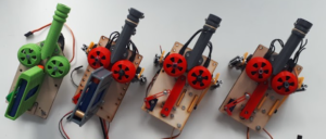
Dynometer
So I wondered if it's possible to create a stationair dynometer setup, for at least calibrating the systematical influences.

By placing both wheels on top a accurate sensors, the real wheel distance could be computed. So TicksToDist & TicksLR should be measurable very accurate, with an Arduino Mega.
Read the team post about the details: Tooling - Dynometer.
Conclusion
Calibration is an interesting topic and I’m just starting to understand a bit more about odometry and the way our RTC works. Although we do realize this dynamometer will not solve all issues, potential only reducing (some?) systematic errors.
Like just moving in a straight line, calibrating wheel diameter differences might be a good option. But driving different floor types will result in different none-systematic errors. So final calibration will always depend on the floor & speed you drive.
When wheel distance over certain time in known, the dynometer should be able calculating actual speeds too. Well, this did not work very precise either. The difference between a moving robot and this platform is a difference in inertia.
So when a robot starts to move or slows down, inertia icw. PID settings will have influence on the actual robot speed and so the final position. In other words, the static robot will react different, then a moving robot.
Potential improvements:
Having 2 sensor wheels (with it's own frictionless wheel support), positioned next to both drive wheels and the assumption these sensor wheels are not slipping, both none- and systematic errors might be automatically corrected for. That might help a more easy calibration.
An other option, might be using the camera & measuring reference points. When the robot comes close to the end position, it could compute it's error and compensate for that.
Well, maybe a nice side project for another moment in time... 😉